
Integrating Risk-Based Inspection
Recommendations with Inspection
Programs and Integrity Operating
Windows
Lynne Kaley, PE
W. Clay White
Principal
Fixed Equipment Network Lead
Trinity Bridge, LLC
Phillips 66
Savannah, GA
Houston, TX

Introduction
Risk-Based Inspection (RBI) has been widely used to optimize
inspection activities in the industry starting in the 1990’s
RBI for pressure vessels has been generally accepted and easily
managed
Application to piping corrosion loops/systems in a manageable way
has been more challenging
Establishing Integrity Operating Windows (IOW’s) using API 584 is
an opportunity to manage fixed equipment and piping and integrate
inspection activities with RBI
Need to outline the steps for defining a piping inspection program
using risk with corrosion loop & circuit definition and identification
of IOW’s
Discuss challenges to inspection planning using risk for piping
corrosion loops
Work Process

Establish risk approach and basis for inspection plan development
(inspection date, methods and coverage)
Determine RBI unit scope, including fixed equipment and piping
boundaries (typically includes primary piping and bypasses but not
including utilities piping and piping after PRDs)
Organize updated unit drawings and relevant data for analysis –
P&IDs, PFDs, not necessarily including piping isometrics
Define corrosion loops and naming convention
Circuitize piping within each corrosion loop
Conduct material/corrosion of all equipment included in unit study
Create an database for calculation of risk and development of
inspection plans
Calculate Risk
Establish IOWs
Develop Inspection Plans

Considerations for Integrating RBI, IOWs
and Piping Inspection
Model Corrosion Loop as Equipment; Circuit as a component
– Setting values to represent properties to model circuit
– Circuit comprised of various components with varying rates,
thicknesses and other properties
When using RBI for piping inspection consider:
– Basis for RBI modeling may not be representative for all components
of the circuit, such as diameter, pressure, corrosion rate, corrosion
allowance and t-min
– Using average circuit corrosion rate from TML’s/CML’s may be non-
conservative
– Thicknesses of components in the circuit may vary
Be careful when using a single thickness measurement and
corrosion rate for multiple TML’s/CML’s

Definition of Corrosion Loops
Corrosion Loop must be properly defined:
– Corrosion Loops defined as equipment controlled together
– In similar operating service
– Expect similar corrosion mechanisms and rates
– Share IOW criteria alerts and alarms
– Controlled together operationally
Crude Unit PFD &
Corrosion Loops
APOR RETURN
KEROSENE DR
STRIPPER
COLD CRUDE
ACUUM

CRUDE FROM S TORAGE

WASH SUPP LY


WASH RETURN
PREHE AT EXCHANGERS

DESA
L
TER
T
O CRUDE
C
O
L
UMN

CRUDE HE ATER


HOT CRUDE


PREHE AT EXCHANGERS


CRUDE


COLUMN


KEROSENEV


CRUDE


COLUMN


CRUDE


COLUMN


CRUDE


COLUMN


CRUDE


COLUMN

OVRHD CONDENSERS
OVRHD DRUM


KEROSENE


STRIPPER


AW


KEROSENE


STRIPPER REBOILER


LAGO UPPER REFLUX


LAGOVAPOR RETURN


LAGO


DESA
L
TER CRUDE/


CIRC. LAGO EXCHANGER


CRUDE BOT
T
OMS
T
O
V
NAPHTH
A


KEROSENE


LAGO


LAGO


AGO


STRIPPER


AGO


TOWER

Define Circuits
Goal: To create common inspection strategies for each circuit
Corrosion Circuit must be properly defined:
– Equipment with the same expected corrosion mechanisms and rates
– Same material of construction
– Same or very similar operating conditions
– Equipment thickness measurements and calculated corrosion rates
should be manageable as a group
Define piping boundaries
– Include all primary piping
– Piping bypasses, start-up/shut-down lines
– Piping up to PRD’s
– Normally does not include utility piping (e.g. air, nitrogen, steam), PRD
relief system downstream piping

Establishing IOW’s
Based on Damage Review Conducted
– 2 Approaches, Historical Operating & Limiting component
– Identify potentially active damage mechanisms for all fixed equipment and
piping corrosion loops/circuits
– Assign estimated or measured damage based on service experience
– Identify process variables driving in-service damage
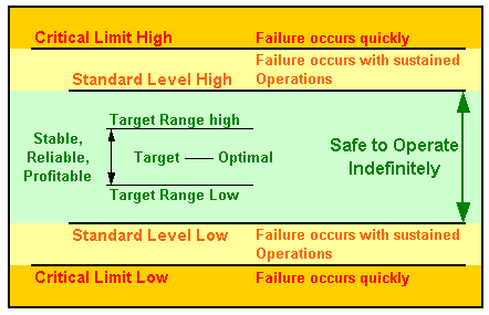
Established limits for process variables affecting the integrity of
equipment
Identify process operation deviating from established limit for a
predetermined amount of time
– Operating variables effecting reliable operation of the equipment
– Operating variables determined as Critical, Standard and/or Informational
– Appropriate limits for Critical and Standard windows
Critical and Standard limits are normally established for a corrosion loop or
system but are based on the equipment or component limiting the
corrosion loop


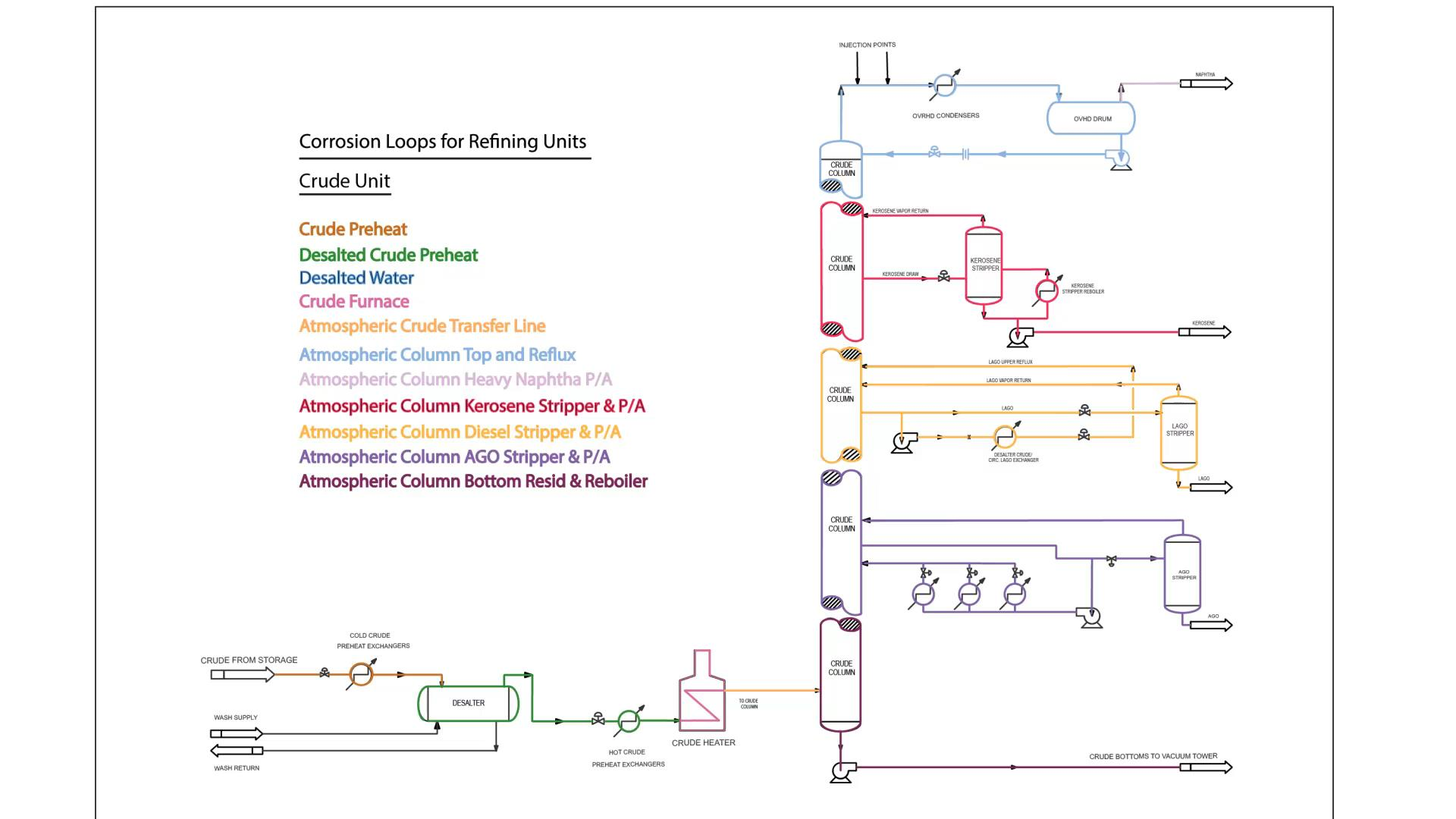

Corrosion Loop Description
Consists of the overhead of Crude Distillation Column through
Overhead Condensers and to Overhead Accumulator
Operates at an average pH of 6.0 (range of 4.8 to 8.0). Operating
temperature ranges from 221OF to 122OF. The primary concerns in
this loop are hydrochloric acid corrosion at or below the dew point
and mix point/injection point corrosion near each of the injection
points. All piping in this loop is carbon steel materials of
construction.
Specific Corrosion Mechanisms:
– Chloride corrosion due to Hydrochloric Acid for all materials of construction at
temperatures below water dew point.
– Injection/Mix point corrosion (localized) due to use of ammonia, inhibitor and
neutraliser use.
– SSC and HIC/SOHIC in Wet H2S service.
– Corrosion Under Insulation (CUI) potential at temperatures less than < 177OC
(350OF)
