
Using Risk-Based Approaches to Define
and Adjust Condition Monitoring
Locations, Inspection Techniques and
Intervals

By: Lynne Kaley & Virginia Edley
•
•
•
•
•
•

Lynne Kaley, PE
Materials/Corrosion and Risk Management Engineer
30+ Years Refining, Petrochemical and Midstream Gas Processing
Experience
10 years owner/user plant metallurgist/corrosion and corporate
engineer
20+ years consulting with plant management, engineering and
inspection departments:
– Risk-Based technology (RBI) development leader
– Development of implementation work process for plant application
– Member of API committees for development of API 580 and API 581
recommended practices
Project Manager of API RBI Project from 1996-2009
Master Editor for API 581
•
•
•
•
•
•
Virginia Edley
Mechanical/Inspection and Reliability Engineer
30 Years Refining, Petrochemical and Oil and Gas Experience in
Maintenance, Inspection and Reliability
20+ years owner/user inspection engineer, inspection program
manager, reliability manager
Extensive experience in working with existing inspection
organizations and developing practical strategies for program
improvement
Actively involved in the API RBI development project and
implementation of API RBI programs in a number of plants as an
owner/user and as a consultant
Master Editor for API 585
•
•
Purpose
Purpose of the Presentation
– Develop a process for using risk-based results to define
methods, extent and frequency of inspection for piping
– Present a way to optimize CML’s
– Present an inspection prioritization method to be used
with or without quantitative RBI
Sources
– API 570
– API 510
– API 580
– API 581
•
•
•
•
•
•
•
•
Outline
Defining piping circuit CML’s
Maintaining CML’s
Guidance from the API Codes
A Risk Based Process to guide CML placement
Example – Piping Circuitization
Example – Crude Preheat Piping CML placement
Example – Coker LSR Reflux Piping CML
placement
Conclusion/Summary
•
•
•
Piping Circuit CML’s
How many CMLs are needed to monitor for
General Thinning only?
How many CMLs are needed to monitor for
Localized Thinning?
Is more thickness data better?
•
•
•
•
•
Setting Up CML’s
Identify locations on drawings and pipe
Set up equipment, component and circuits in
database
Identify applicable specifications, material of
construction and design pressure & temperature
Document starting thickness and service start
date
Identify minimum thickness and/or alert
thickness
Evaluate corrosion rate
•
•
•
•
•
Maintaining CML’s
Conduct Inspection
– Access to location
– Calibrate properly
– Take measurements
– Record measurement
Input readings in database
Perform calculations
and Remaining Life
Schedule next inspection
Reschedule
Conduct
Inspection


Analyze
Input


Data
readings

Perform


Calculations
•
•
API 570 Guidance (5.6.3)
A decision on the type, number and location
of the CML’s should consider results from
previous inspections, the patterns of corrosion
and damage that are expected and the
potential consequence of loss of containment.
In theory, a circuit subject to perfectly uniform
corrosion could be adequately monitored
with a single CML.
•
API 570 Guidance (5.6.3)
Inspectors must use their knowledge of the
process unit to optimize the CML selection for
each circuit, balancing the effort of collecting
the data with the benefits provided by the
data.
•
•
API 570 Guidance (5.6.3)
More CML’s should be selected for piping systems with any of the
following characteristics:
– a) higher potential for creating a safety or environmental emergency in
the event of a leak;
– b) higher expected or experienced corrosion rates;
– c) higher potential for localized corrosion;
– d) more complexity in terms of fittings, branches, deadlegs, injection
points, and other similar items;
– e) higher potential for CUI.
Fewer CML’s can be selected for piping systems with any of the
following three characteristics:
– a) low potential for creating a safety or environmental emergency in
the event of a leak;
– b) relatively noncorrosive piping systems;
– c) long, straight-run piping systems.
•
•
•
Risk Based Inspection Codes
RBI may be used to determine inspection
interval, type and extent of future
inspection/examinations (API 570)
API 580 provides no guidance on specific type
and extent of inspection based on risk levels
API 581 provides examples of various types of
inspection for various damage types, coverage
and extent
Risk Based Inspection
• Any RBI methodology requires:
– POF – COF used in a matrix and generates a risk
category
– Credible corrosion/materials review for current
operating conditions
– Understanding of process operation including normal
operation, upsets and start-up/shutdown
– Review and consistent credit for historical inspection
– Does not require quantitative, highly technical
approach to be credible
Note: Use of a qualitative approach requires more
expertise and qualified practitioners.
•
•
•
Risk Based Inspection
Corrosion System must be properly defined:
– Corrosion Systems defined as equipment controlled together
– In similar operating service
– Expect similar corrosion mechanisms and rates
– Share Integrity Operating Window (IOW) criteria alerts and
alarms
Corrosion Circuit must be properly defined:
– Equipment with the same expected corrosion mechanisms and
rates
– Same material of construction
– Same or very similar operating conditions
– Equipment thickness measurements and calculated corrosion
rates should be manageable as a group
IOW set by weakest link of circuit per corrosion system
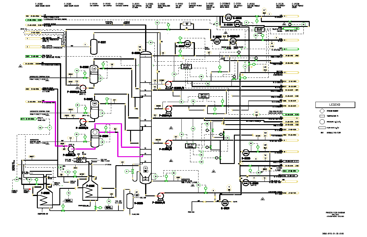
Corrosion System HGO Stripper Pumparound
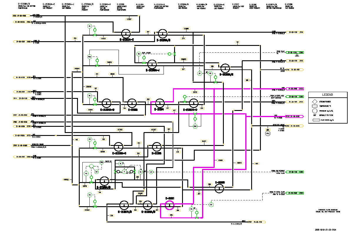
Corrosion System HGO Stripper Pumparound